供应41通道100G高斯AWG密集波分复用器
价格:电议
地区:广东省 深圳市
手 机:13926580923
传 真:0755-29048624
图文详情
产品属性
相关推荐
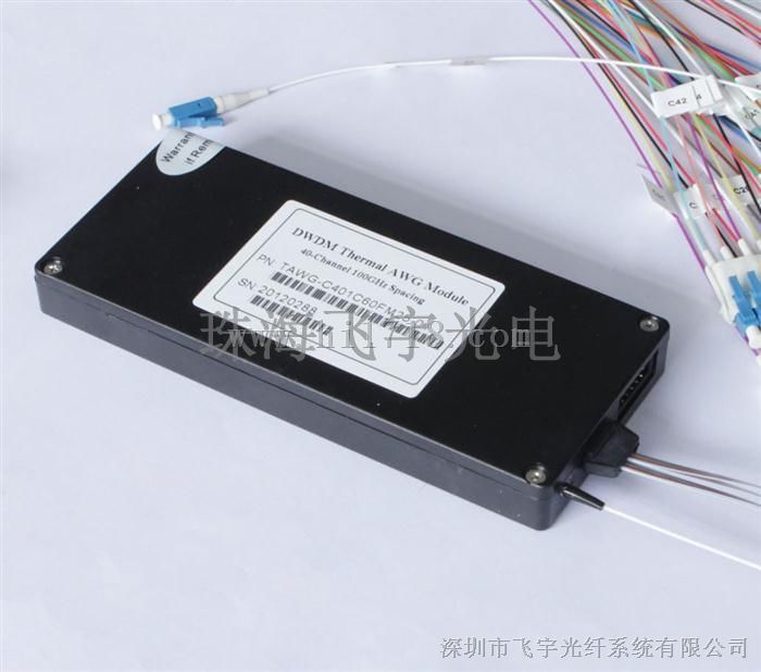
飞宇光点提供各种AWG产品,包括50GHz,100GHz和200GHz的无热AWG(高斯AWG)和有热AWG(平顶AWG),这里给大家展示41通道无热高斯AWG
Athermal AWG(AAWG) have equivalent performance to standard Thermal AWG(TAWG) but require no electrical power for stabilization. They can be used as direct replacements for Thin Film Filters(Filter type DWDM module) for es where no power is available, also suitable for outdoor applicati over -30 to +70 degree in access networks. Flyin’s Athermal AWG(AAWG) provide excellent optical performance, high reliability, ease of fiber handling and power saving solution in a compact package. Different input and output fibers, such as SM fibers, MM fibers and PM fiber can be selected to meet different applicati. We can also offer different product packages, inluding special metal box and 19” 1U rackmount.
The planar DWDM components(Thermal/Athermal AWG) from Flyin Optronics are fully qualified according to Telcordia reliability assurance requirements for fiber optic and opto-electronic components (GR-1221-CORE/UNC, Generic Reliability Assurance Requirements for Fiber Optic Branching Components, and Telcordia TR-NWT-000468, Reliability Assurance Practices for Opto-electronic Devices).
Optical Specification (Gaussian Athermal AWG)
Parameters | Condition | Specs | Units | ||
Min | Typ | Max | |||
Number of Channels |
| 41 |
| ||
Number Channel Spacing | 100GHz | 100 | GHz | ||
Cha. Center Wavelength | ITU frequency. | C -band | nm | ||
Clear Channel Passband |
| ±12.5 | GHz | ||
Wavelength Stability | Maximum range of the wavelength error of all channels and temperatures in average polarization. | ±0.05 | nm | ||
-1 dB Channel Bandwidth | Clear channel bandwidth defined by passband shape. For each channel | 0.24 |
|
| nm |
-3 dB Channel Bandwidth | Clear channel bandwidth defined by passband shape. For each channel | 0.43 |
|
| nm |
Optical Insertion Loss at ITU grid | Defined as the minimum transmission at ITU wavelength for all channels. For each channel, at all temperatures and polarizati. |
| 4.5 | 6.0 | dB |
Adjacent Channel Isolation | Insertion loss difference from the mean transmission at the ITU grid wavelength to the highest power, all polarizati, within the ITU band of the adjacent channels. | 25 |
|
| dB |
Non-Adjacent, Channel Isolation | Insertion loss difference from the mean transmission at the ITU grid wavelength to the highest power, all polarizati, within the ITU band of the nonadjacent channels. | 29 |
|
| dB |
Total Channel Isolation | Total cumulative insertion loss difference from the mean transmission at the ITU grid wavelength to the highest power, all polarizati, within the ITU band of all other channels, including adjacent channels. | 22 |
|
| dB |
Insertion Loss Uniformity | Maximum range of the insertion loss variation within ITU across all channels, polarizati and temperatures. |
|
| 1.5 | dB |
Directivity(Mux Only) | Ratio of reflected power out of any channel(other than channel n)to power in from the input channel n | 40 |
|
| dB |
Insertion Loss Ripple | Any maxima and any minima of optical loss across ITU band, excluding boundary points, for each channel at each port |
|
| 1.2 | dB |
Optical Return loss | Input & output ports | 40 |
|
| dB |
PDL/Polarization Dependent Loss in Clear Channel Band | Worst-e value measured in ITU band |
| 0.3 | 0.5 | dB |
Polarization Mode Dispersion |
|
|
| 0.5 | ps |
Maximum Optical Power |
|
|
| 23 | dBm |
MUX/DEMUX input/ output Monitoring range |
| -35 |
| +23 | dBm |
IL Represents the worst e over a +/-0.01nm window around the ITU wavelength;
PDL was measured on average polarization over a +/- 0.01nm window around the ITU wavelength.