供应COMPEX各类电容
价格:电议
地区:上海市
电 话:021-58317807
手 机:18321153181
图文详情
产品属性
相关推荐
Our continuing philosophy of specializing exclusively in single layer parallel plate microwave chip capacitors has enabled Compex to attain a position of leadership in this area. We now offer the broadest variety of chip types, sizes, values and tolerances available today. This along with individualized attention, quality and on time delivery has helped create a wonderful bond of loyalty between Compex and our many customers both domestically and internationally.
We look forward to continuing to provide you, our customer, the product, quality, service and delivery so vital to your success.
Compex Corp NOW offers 48 hr. guaranteed delivery on Microwave CSA Ceramic Capacitors (single layer) from 50 to 500 chips.
*Dimensions guaranteed not to exceed 10, 20 and 30 mil width
.01-.9 pF capacity
Cap pF | Case Size 10 | Case Size 20 | Case Size 30 |
.06 | CSA-50-10x10Mx10-G-R06-M | | |
.08 | | CSA-30-16x16x10-G-R08-M | |
.1 | CSA-50-10x10Mx6-G-R10-M | | CSA-20-28x28x7-G-R10-M |
.2 | | CSA-50-17x17-10-G-R20-M | |
.3 | CSA-60-10x10Mx6-G-R30-M | | CSA-30-26x26x5-G-R30-M |
.4 | | CSA-50-17x17x5-G-R40-M | |
.5 | CSA-70-10x10Mx6-G-R50-M | | CSA-50-27x27x10-G-R50-K |
.6 | | CSA-55-18x18x7-G-R60-M | |
.8 | CSA-75-10x10Mx7-G-R80-M | | CSA-50-26x26x6-G-R80-K |
Corporation
1.0-5.0 pF capacity
Cap pF | Case Size 10 | Case Size 20 | Case Size 30 |
1.0 | | CSA-60-17x17x6-G-1R0-M | |
1.2 | CSA-75-10x10Mx5-G-1R2-M | | CSA-50-26x26x4-G-1R2-K |
1.5 | | CSA-60-17x17x4-G-1R5-M | |
1.8 | CSA-90-10x10Mx10-G-1R8-M | | CSA-55-27x27x5-G-1R8-K |
2.0 | | CSA-70-17x17x5-G-2R0-M | |
2.2 | CSA-90-10x10Mx8-G-2R2-M | | CSA-55-27x27x4-G-2R2-K |
2.7 | | CSA-75-17x17x7-G-2R7-M | |
3.3 | CSA-90-10x10Mx6-G-3R3-M | | CSA-60-26x26x4-G-3R3-K |
3.9 | | CSA-75-18x18x5-G-3R9-M | |
4.7 | CSA-90-10x10Mx4-G-4R7-M | | CSA-70-26x26x5-G-4R7-K |
5.1-30 pF capacity
Cap pF | Case Size 10 | Case Size 20 | Case Size 30 |
5.6 | | CSA-90-17x17x10-G-5R6-M | |
6.8 | CSA-100-10x10Mx6-G-6R8-M | | CSA-75-26x26x6-G-6R8-K |
8.2 | | CSA-90-18x18x8-G-8R2-M | |
10 | CSA-100-10x10Mx4-G-100-M | | CSA-75-25x25x4-G-100-K |
12 | | CSA-90-17x17x5-G-120-M | |
15 | CSA-120-10x10Mx5-G-150-M | | CSA-90-27x27x10-G-150-M |
18 | | CSA-100-17x17x7-G-180-M | |
20 | CSA-130-10x10Mx5-G-200-M | | CSA-90-26x26x7-G-200-M |
22 | | CSA-100-18x18x6-G-220-M | |
27 | CSA-140-10x10Mx5-G-270-M | | CSA-90-26x26x5-G-270-M |
30.1-200 pF capacity
Cap pF | Case Size 10 | Case Size 20 | Case Size 30 |
33 | | CSA-100-18x18x4-G-330-M | |
39 | | | CSA-100-25x25x7-G-390-M |
47 | | CSA-120-17x17x5-G-470-M | |
56 | | | CSA-100-26x26x5-G-560-M |
68 | | CSA-130-17x17x5-G-680-M | |
82 | | | CSA-120-27x27x7-G-820-M |
100 | | CSA-140-18x18x5-G-101-M | |
120 | | | CSA-120-27x27x5-G-121-M |
180 | | | CSA-130-25x25x4-G-181-M |
200 | | | CSA-140-26x26x5-G-221-M |
Corporation
Compex Corporation has characterized many different dielectric materials suitable for high performance chip capacitor applications. These dielectrics are listed as standard (Table 1 and Table 2). Dielectrics characterized but not listed are also available.
CLASS I - This class of dielectrics consists of material exhibiting very low losses, extremely low or closely controlled temperature coefficients, negligible voltage and frequency coefficients, no aging effects, and high insulation and dielectric breakdown.
Type | Ins. Res. Meg-Ohms | Rated Voltage | See TC Curves -55 to | Aging | Frequency Coeff. of C% | Voltage Coeff. of C% | Dissipation Factor 10 GHz | Dielectric Constant (K) |
C-20 | 1,000,000 | 50 100 | Negligible | Negligible | Negligible | Negligible | .0001 | 3.8 |
C-30 | 1,000,000 | 50 100 | P180 ± 50 | Negligible | Negligible | Negligible | .0006 | 10 |
C-50 | 1,000,000 | 50 100 | 0 ± 30 | Negligible | Negligible | Negligible | .0020 | 31 |
C-55 | 1,000,000 | 50 100 | 0 ± 30 | Negligible | Negligible | Negligible | .005 | 55 |
C-60 | 1,000,000 | 50 100 | N750 ± 100 | Negligible | Negligible | Negligible | .0005 | 90 |
C-70 | 1,000,000 | 50 100 | N1500 ± 400 | Negligible | Negligible | Negligible | .0025 | 150 |
C-75 | 1,000,000 | 50 100 | N2200 ± 400 | Negligible | Negligible | Negligible | .003 | 280 |
CLASS II - This class of material is characterized by high dielectric constants, increased losses and higher temperature coefficients. The voltage and frequency coefficients as well as aging effects are no longer negligible. These properties are inherent with this class of material but the high dielectric constants permit the use of smaller size to achieve low series inductance and meet dimensional requirements. Capacitors made with these materials are often used for coupling of microstrip line circuits where the small chip size is necessary. Used as bypass capacitors, the small size provides low series inductance and dielectric losses are of little or no concern.
Compex
Corporation
Type | Ins. Res. Meg-Ohms | Rated Voltage | TC change% | Aging | Frequency Coeff. of C% | Voltage Coeff. of C% at 10V/mil | Dissipation Factor | Dielectric Constant |
C-80 | 100000 | 50 100 | +5-10* | 2.0 | -12 | ±1 | .010 | 280 |
C-90 | 100000 | 50 100 | +10-10* | 3.0 | -6 | ±2 | .015 | 900 |
C-100 | 100000 | 50 100 | +3-10* | 3.5 | -12 | ±2 | .015 | 1900 |
C-120 | 100000 | 50 100 | +5-25* | 3.0 | -12 | ±2 | .020 | 3000 |
C-130 | 100000 | 50 100 | +5-50** | 3.0 | -9 | -10 | .025 | 5000 |
C-1351 | 100000 | 50 100 | +15-15** | 3.0 | -9 | -10 | .035 | 5000 |
C-140 | 100000 | 50 100 | +5-70** | 3.0 | -10 | -50 | .025 | 9000 |
C-160 | 100000 | 50 100 | +5-80** | 3.0 | -10 | -50 | .030 | 16000 |
C-200 | 100000 | 50 100 | +15-15** | 3.0 | -10 | -50 | .015 | 20000 |
1 not currently available in margin caps - please consult factory
Mounting can be accomplished by:
1. Soldering with the use of pre-tinning and solder reflow, solder preforms, solder paste etc.
2.
3. Conductive Epoxy
Termination can be made by:
1. Soldering of wire of ribbon leads (minimum chip size limited by user's soldering techniques).
2. Thermal compression, thermasonic, or ultrasonic bonding with aluminum or gold wire.
3.
Corporation
Compex offers an extensive variety of substrates in both the Class I and Class II categories with dielectric constants ranging from 3.8 to 16000. All substrates can be supplied as follows: Lapping and Polishing to exact specifications. Thicknesses range from 3 mils and up, and length and width to 2 inches depending on ceramic type. |
Compex maintains a stock inventory of our dielectrics in wafer form. We are able to manufacture the finished capacitor to your exact needs in a matter of hours when necessary.
Style Tolerance
Dielectric (milli-inches)
Metalization Capacitance
Corporation
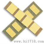
Two Electrode - Series CSA | ||
This classic design is the simplest and most widely used. The chip size, shape and electrical properties may be determined and specified from the dialectric material data and the capacitor selection chart. Chip Sizes: Length or width .007" and up, square or rectangular. Capicitance: 0.08 to 10,000 pF | ||
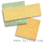
Split Electrode - Series CSB | ||
A single full electrode is provided on one side of the capacitor and split electrodes on the other side. This design opens up a number of application possibilities. This is a three terminal capacitor which can be used as two capacitors with a common electrode or as serially connected capacitors so that connections may be made on one side of the chip only. This design is often used in microstrip coupling to eliminate lead inductance and raise the self resonance frequency. | ||
Compex
Corporation
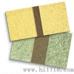
Multiple Values, Custom - Series CAX | ||||
A common electrode on one side of the chip and multiple electrodes on the other side. The capacitor array can be used as individual capacitors on a single chip or as a step adjustable capacitor by connecting combinations of electrodes to achieve the desired capacitance. Please call Compex Corp. for final details and specifications. | ||||
Step Adjustable Array - Series CAD | ||||
The arrays of capacitors are arranged in binary ratios ( | ||||
Row Caps - Series CRO | ||||
Row caps are used where arrays of capacitors (not necessarily identical) are needed, usually for decoupling/bypass of GaAs integrated circuits. Values up to 1000 pF per capacitor. Up to 8 capacitors per array are available. Typical overall dimensions range from 20x65 mils to 40x125 mils. Call Compex with your requirements. | ||||
Margin Caps - Series CSM | ||||
Margin caps have the topside electrode withdrawn from the edges in order to increase the distance between electrodes and dramatically decrease the possibilities of shorting when epoxy die mounting. This style is also widely used for optical recognition based assembly. | ||||
COMPEX
单件包装
工业电力电气设备