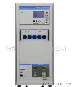
Lightning Surge Simulator
LSS-15AX Series
Conforming to IEC 61000-4-5
LSS-15AX Series brochure PDF(1881Kbyte) for additional product information. <Limited Time Offer>
Buy NoiseKens LSS-15AX series ang get free"Lightning Surge Immunity Testing Manual."
Manual SampleEnglish
GENERAL
Surges represent transients that might be induced in cables by lightning.By their nature, fairly high energy charges may easily damage or upset unprotected electronics circuits and components.Surges are not a new problem.Many companies have been testing their products at various stages of the products life: design tests, qualification tests, production tests and diagnostic tests.
The advance of surge suppression devices and technique does not lessen the importance of surge testing, but rather increases it, as the requirement to reduce power consumption and to increase the operational speed of semiconductors has become more demanding. In addition, the issue of surge testing is attracting renewed interest since this form of immunity is now a must for almost all electronic products for access to the global market.
|
Fully compliant with the requirements called for in the 2ndedition of IEC 61000-4-5 standard, the LSS-15AX series simulators provide a testing facility for up to 15kV test voltage without sacrificing safety and ease of use. The LSS-15AX simulators generate the two combination pulses 1.2/50 µs (8/20 µS) and 10/700 µS (5/320 µS).
- Fully programmable and easy to use simulator that meets andfar exceeds theIEC 61000-4-5 (2ndedition)requirements
- 15kV testing
- Advanced safety
- Flexible test sequencing with Program Mode
|
| Very intuitive settings can be done by the assistance of the well configured user-interface consisting of a 5-inch LCD, ten-key, functions keys and others. Coupling modes are graphically shown, allowing the operator to select the desired mode and allows easy reference of settings when the test is in progress.
| | This button, easily accessible and placed on the front panel, enables the operator to stop the generation of the pulses anytime he/she desires. In addition to the high voltage power, the operator can turn off the EUT.
| | A safely interlock is provided through the special design high voltage connector. The high voltage circuitry never be activated when the connector is not correctly positioned or not firmly locked.
| | The value of the actual peak amplitude is measured and shown for both voltage and current.
|
|
| - Automatic stop by detecting breakdown
| The simulator automatically stops generating the pulses if the peak current measured exceeds the threshold limit which can be freely set as the breakdown criteria.
| | |
Item| LSS-15AX A1A/A3A | LSS-15AX C1A/C3A Surge generating
unit | Output waveform
Open circuit voltage (short circuit current) | 1.2/50µs(8/20µs) | 1.2/50µs(8/20µs)
10/700µs(5/320µs) | | Output voltage/current | 15kV/7500A | 15KV/7500A (1.2/50µs)
15KV/375A (10/700µs, at output 40 ohm) | | Surge switching element | By Ignitron | | Output polarity | Positive or negative | | Surge repetition cycle | 20 sec. | 20 sec. (1.2/50µs)
30 sec. (10/700µs) | | Output impedance | 2 ohm | 2 ohm (1.2/50µs)
40 ohm (10/700µs) with limiter resister | | AC/DC lines CDN | Injecting surge waveform | 1.2/50µs | | Injecting surge voltage/current | 15kV/7500A maximum | | Surge coupling | Between line and line:18µF
Between line and PE: 10 ohm+9µF | | AC Power capacity | A1A/C1A: Single phase,AC240V/30A | | A3A/C3A: Single phase 3-phase, AC600V/50A | | Voltage drop | 9V at 25A, 11V at 30A, 18V at 50A | | DC Power capacity | DC60V/20A | | Decoupling coil | 1.5mH (each phase) | | Decoupling capacitor | 10µF (Between line and line, between line and PE) | | Coupling phase angle control | 0 to 360° (at 1°step) | | Residual voltage | <15% of test voltage or twice of rated voltages (peak) of EUT | | Communication lines CDN | Injecting surge waveform |
| 1.2/50µs
10/700µs | | Injecting surge voltage | 15kV max. | | Matching resistance | 40 ohm (1.2/50µs)
25 ohm (10/700µs ) | | Total line number | 4 lines | | Decoupling coil | 20mH(each phase) | | Power capacity of EUT | DC50V 100mA | | Voltage/ current monitor output | Voltage/current monitor output ratio | 1/2000 (voltage monitor), 1000A/V (current monitor) | | Check circuit method | Waveform measuring method by magnetic coupling | | Auto control functions | Surge generating unit | - Polarity selection
- Surge output port selection
| - Surge waveform selection
- Polarity selection
- Output port selection
- 10/700µs limiter resister selection
| | AC/DC lines CDN | ·Surge injection phase changing
·Surge return phase changing
·Coupling element changing | | Communication lines CDN |
| | · | Matching resistance selection | | · | 2 lines/4 lines selection | | · | Surge return line selection |
| | Application function | Operation mode | ·Manual test mode
·Program test mode | | Voltage/current monitor function | ·Peak level display
·Break down detecting | | External interface | Communication function | RS-232C(Optional), GP-IB (Optional) | | Power supply | AC90 to 120/200 to240V 50/60Hz | | Dimensions (W)x(H)x (D)mm | 555x1250x790mm (A1A)
555x1500x790mm (A3A) | 555x1500x 790mm (C1A)
555x1800x790mm (C3A) | | Weight | Approx. 200 kgs (A1A)
Approx. 320 kgs (A3A) | Approx. 270 kgs (C1A)
Approx. 340 kgs (C3A) |
|
The following menus can be selected in the menu display.
- Manual mode test
- Program mode test
- Utilities
- Snap shop: Display image (Bit map form) can be saved in a memory card and can be used for making reports, etc
| | MANUAL MODE TEST SETTING DISPLAY (1)
When manual mode test is selected in the menu display, the corresponding test setting display will be shown. The output voltage, waveform and other test parameters can be set. Unnecessary items are indicated lightly and the simulator does not accept change in setting. |
| | MANUAL MODE TEST SETTING DISPLAY (2)
Some items can be selected on pop up menus. The right example shows the choices on "Output To".
|
| | AC/DC INJECTION SETTING DISPLAY
Press the coupling mode key. Coupling mode selection screen will appear. The example shows the 3-phase AC CDN screen on which coupling and return lines can be set. On the telecom CDN setting screen the number of lines (2 or 4 lines), limit resistance (25 ohm or 40 ohm) and return line (1, 2, 3, 4 or PE) can be set. |
|
TEST SET UP EXAMPLE
Capacitive coupling on single-phase AC lines in Line-to-line & line-to-ground mode
|
The following accessories are included.
- AC line input cable (4-core: 2m): 1pc
- DC line input cable (3-core: 2m): 1pc
- Surge output cable for surge output (2m) : 2 pcs
- Surge output cable for injection line (2m) : 5 pcs
- Monitoring coaxial cable (1m): 2 pcs
- PE cable (for main unit: 2m): 1pc
- PE cable (for injection line: 2m): 1pc
- Interlock connector: 1pc
- Instruction manual: 1 pc (English)
- Connector caps (7pcs) are fitted to the main unit when it leaves our factory.
Series
Conforming to IEC 61000-4-5
LSS-15AX Series brochure PDF(1881Kbyte) for additional product information. <Limited Time Offer>
Buy NoiseKens LSS-15AX series ang get free"Lightning Surge Immunity Testing Manual."
Manual SampleEnglish
GENERAL
Surges represent transients that might be induced in cables by lightning.By their nature, fairly high energy charges may easily damage or upset unprotected electronics circuits and components.Surges are not a new problem.Many companies have been testing their products at various stages of the products life: design tests, qualification tests, production tests and diagnostic tests.
The advance of surge suppression devices and technique does not lessen the importance of surge testing, but rather increases it, as the requirement to reduce power consumption and to increase the operational speed of semiconductors has become more demanding. In addition, the issue of surge testing is attracting renewed interest since this form of immunity is now a must for almost all electronic products for access to the global market.
|