
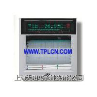
PMA记录仪KS3930B
价格:电议
地区:上海市
电 话:021-51087286
手 机:13817574499
传 真:021-51079786
图文详情
产品属性
相关推荐
Line recorder KS 3930A KS 3930B
Galvanically isolated input channels for simple connection
Measuring and recording range freely configurable
Maintenance-free recording system
Universal cassette for roll or Z-fold chart paper
6 limit values with free channel allocation
Optional:
isolated 24 VDC output
digital input &output
Additionally with KS 3930 A:
Alpha-numeric printing system for recording date, time,
texts, and other information
PROFILE
The KS 3930 is an industrial line recorder with microprocessor control and max. 3 channels. Its front dimensions are 144 x 144 mm.
There are two basic versions:
KS 3930 B
This is a low-cost recorder with two different input circuits:
a) Standard
For DC input (e. g. standard
0/4. . .20 mA or 0. . .10V signals).
b) Universal
Extended measurement value table for DC signals (mA, mV,V),thermocouples, resistance thermometers and potentiometric transducers.
KS 3930 A
This version offers the same functions as the KS 3930 B, but is always fitted with the universal input circuit.
Furthermore , it also has:
– an alpha-numeric printing system for recording date, time, texts, event marking, measurement value table,etc.
Both basic versions are freely programmable without any accessory equipment. Alternaternitively, the recorders can be configured remotely,
from a PC which is connected via a front-panel interface socket. A suitable Engineering Tool is available as a software package.
With numerous functions and robust construction, the KS 3930 A/B line recorders are ideal for universal industrial applications.
OPERATING PRINCIPLE
1、The input channels are polled by a wear-free semiconductor scanner which also provides galvanic isolation.The A/D converter works with high
resolution, so that even small measuring spans can be processed accurately.
2、Non-linear input signals, e.g. from thermocouples and resistance thermometers, are corrected, so that
display and recording are temperature-linear.
3、The microprocessor controls the stepping motors for chart drive and the recording systems. Digital technology eliminates wear-prone components
such as DC motors, cord drives, and feedback potentiometers, so that the recorders are practically maintenance-free.
CONSTRUCTION
1、The recorder is fitted in a sheet-steel housing for panel nounting. The front door gives protection type IP54 (splash
water).
2、The chassis is retained in the housing by means of a locking lever. After unlocking, the chassis can be drawn
forwards, e. g. for convenient pen replacement. For servicing, the chassis can be removed completely.
3、A ribbon cable with plug connects the chassis with the CPU. The power supply is fitted to the housing rear, thus ensuring good heat convection and minimum self-heating of the recorder.
4、A universal chart cassette permits using Z-fold or roll charts. For roll charts, a take-up spool is delivered with the
accessories. The paper start is caught and wound up automatically.
TECHNICAL DATA
INPUT
Measurement inputs
No. of channels: 1, 2 or 3, galvanically isolated via semiconductor switches. Max. voltage against protective earth:24 VDC
Excess voltage protection is provided by Varistors.
Measurement principle
A/D conversion according to the Dual-Slope-Method
Resolution: 14 bits
Channel cycle time: 40 ms with 50 Hz
Permissible continuous overload
Max. 24V, max. 40 mA
Interference suppression
Common mode: 90 dB with 50 Hz
Series mode: 60 dB with 50 Hz
Signal attenuation
1st-order low-pass filter adjustable 0-1-3-10-30-100 s or with automatic matching to chart speed.
Reference conditions
Ambient temperature: 21...25 hC
Relative humidity: 50...60%
Source resistance: < 1kΩ
Potential difference: < 1V
STANDARD INPUT (U / I)
Measurement cycle
Normal: 240 ms
Fast: 150 ms
Input resistance
Direct voltage: 100kΩ
Direct current: 50Ω
Measurement ranges
UNIVERSAL INPUT (U / I /TC / RTD / R)
Measurement cycle
Normal: 300 ms
Fast: 180 ms
Input signals
Direct voltage (U)
For input signals ≤ 100mV:
Input resistance > 10MΩ
Source resistance < 10kΩ
For input signals ≥1V:
Input resistance 100kΩ
Direct current (I)
Input resistance 50Ω
Thermocouples (TC)
Input resistance > 10MΩ
Internal or external cold-junction
compensation configurable.
Error of internal CJC: approx. 0,5K
Reference temperature of external CJC:configurable for 0, 20, 50, or 70 hC via reference channel.
Action on sensor break: configurable for < 0 or > 100% of recording range
Resistance thermometer (RTD) and potentiometric transducer (R)
Connection with 3 or 2 leads configurable.
With 2-lead connection, lead resistance must be adjusted to 10?.
Recording range
Freely configurable within the selected input span, for example:
Pt100, input span –200...850 hC
Recording range –50...80 hC
DISPLAY AND RECORDING
Display and recording range
Freely configurable within the selected input span by means of ?Value left“ and ?Value right“.
Scale
3 separate scale strips, each with one graduation.
Length: 100 mm
Drive for recording system
Program-controlled stepping motor.
Resolution: 0,1 mm
Slewing speed: max. 40 mm/s
Recording width: 100 mm
Mechanical recording error
≤0,35% of recording width
Recording pens
Replaceable.
Automatic pen lift when recording stops.
Colours: red (1), blue (2), green (3)
Trace length: approx. 2000 m
Pen life: max. 6 months
Storage life: approx. 2 years
Pen offset with multi-channel versions:1,5 mm
Chart drive
Program-controlled stepping motor.
Step length: 0,02 mm
Chart speed: 0-1-1,25-2,5-5-10-20-60-120-300-600-1200 mm/h,configurable
Chart paper
Universal cassette for Z-fold or roll charts to DIN 16 230
Chart width: 120 mm
Recording width: 100 mm
Z-fold charts Length 16m, fold depth 40 mm, visible chart 30...80 mm
Roll charts Length 31 m, visible chart 70...80 mm,automatic chart take-up
ONLYWITH VERSION KS 3930 A
Alpha-numeric printing system
Replaceable pen, black.
Useful life: approx. 100 000 characters
Printing speed: 0,4 characters/s
– The following are printed:
1、Date, time, chart speed, one recorder and up to 6 event texts.Max. 20 characters per text.Printing is cyclical or triggered by an alarm or external signal.
2、Measurement value table, cyclical every 1, 2, 3, 4 or 12 hours, or triggered by an alarm or an external signal.
3、Limit lines and alarm marks along the recorded trace.
4、 Configuration data.
5、Scale graduation every 20 mm,divisions configurable from 1/1 to 1/7
6、2 event channels for recording ON/OFF signals, triggered by an alarm or an external signal.
Real-time clock
For printing of date/time in 12 or 24-hour mode, summer/winter time switch-over.
Clock is buffered with built-in CR2032 lithium battery, useful life > 3 years with recorder switched off.
OPERATION
By means of built-in keys and display elements.
Operating level
Start/Stop of recorder
Fast chart speed
Programming level
Measurement and recording ranges、Alarm settings、Chart speed and other functions.
Testing level
Test functions、Service functions、Program blocking and other functions.
PC interface
For remote configuration and polling ofmeasurement values via a PC.The interface socket is accessible from
the front. The necessary adapter cable and Engineering Tool software must be ordered separately, see ?Accessories“.
ALARMS
6 limits values, configurable for MIN or MAX operation, free allocation to the recording channels. Switching hysteresis of alarm output:
2% of recording range
OPTIONS
Digital inputs/outputs
Control inputs:
Quantity: 4 (DI1...DI4), passive,
galvanically isolated via opto-coupler
Switching levels:
Low: –3...+5V
High: +8...+30V
Input resistance: > 5kΩ
Signal duration: > 5 seconds
Max. 4 of the following functions can
be selected and allocated to the inputs:
Chart-speed switch-over A/B Start/Stop of recording
1...6 event texts, 1 recorder text
2 event channels, measurement value table
Fast/slow recording
Chart feed 10 to 100 mm
Summer time . . . etc.
Alarm outputs:
6 output relays with potential-free switch-cover contacts.
Contact rating: max. 50 V, 1 A, 30W or 60 VA
Voltage output
24 VDC, ± 15%, max. 75mA,
short-circuit proof, galvanically isolated,capacitive load max. 33mF.
Used e.g. for:Two-wire transmitter supply or for energizing the control inputs.
POWER SUPPLY
AC voltage
230V, 115V or 24V, 47...64Hz
Tolerance range: –20...+15%
Power consumption: approx. 20 VA
DC voltage
24 VDC, –20...+15%, approx. 13W
ENVIRONMENTAL CONDITIONS
Permissible temperatures
For operation: 0...50 hC
For storage: –25...70 hC
Climatic category
KWF to DIN 40 040
Relative humidity ≤75% yearly average,
no condensation
Vibration test: IEC 68-2-6
Mounting position
Front vertical with max. ± 15°
inclination to DIN 16 257.
CONFORMITY TESTS
The instrument has CE-marking.
Electrical safety
Meets EN 61 010-1.
Excess voltage category II
Contamination degree 2
Protective class I (protective earth connection) to VDE 0411, Part 1
Electromagnetic compatibility
Complies with EN 50 081-1 and
EN 50 082-2.
Meets NAMUR recommendation NE 21.
GENERAL
Housing
For mounting in a panel cut-out.Material: sheet steel, grey finish Transparent plastic door with catch.For dimensions, see Fig. 1 Mounting to DIN 43 834-A-230.
Protection mode
According to IEC 529 (EN 60 529)
Front with door: IP 54
Terminals: IP 20
Electrical connections
Signal inputs:Screw terminals for max. 2,5 mm” solid or 1,5 mm” flexible with sleeve
Control inputs and alarm outputs:Via 25-pin D-type connector socket (plug is provided with recorder)
230/115 VAC supply:Appliance connector to IEC 320.(plug is provided with recorder)
24VAC/DC supply:Screw terminals
Weight:approx. 4 kg (5,5 kg packed weight)
Packaging dimensions:Overall: 490 x 290 x 290 mm
Statistical article code:HS-Code
Accessories
PMA
贸易商
美国
