-
图文详情
-
产品属性
-
相关推荐

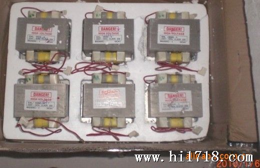
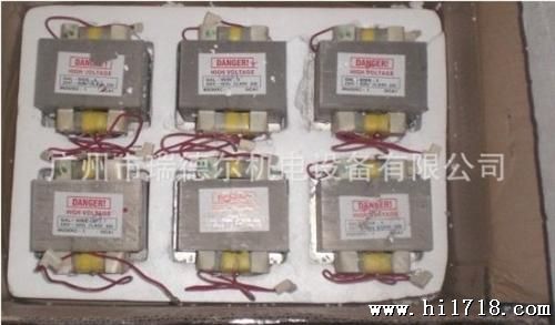
变压器在微波设备中起重要作用,该款变压器质量好价格优欢迎选购!
微波炉变压器-漏磁变压器带有一个带磁分路的铁心,一个初级绕组,两个次级绕组,初级绕组加220v,50hz的电压,次级低压绕组提供的电压供磁近管灯丝加热,次级高压绕组提供的高压交流电路倍压整流变成直流高压给磁控管,使磁控管震荡超高频微波2M167B-M11水冷磁控管参数:
*Filament Current | 4.1.1 | tk=120s | If | 10 | 8 | 12 | A |
Peak Anode Voltage | 4.3.1 | (6) | ebm | 4.10 | 3.90 | 4.30 | kV |
Average Output Power (1) | 4.3.3.1 | (6) | Po(1) | 900 | 860 | - | W |
Frequency | 4.3.4 | - | f | 2460 | 2450 | 2470 | MHz |
Note
(1) The tube shall be mounted on the output coupler (shown in the attached drawing) or similar one. Ambient temperature is 25℃and cooled by forced 1000L/min.
Single phase full wave rectifier without filter shall be used for power supply.
(2) The point for measuring anode/Tp and filter case/Tc temperature are shown in the outline drawing.
(3) In an abnormal condition (without load in the cavity), the maximum allowable anode temperature is 300℃, provided that the operation time does not exceed 30 minutes per operation and the dwell time at the anode temperature 240~300℃does not exceed 25 hour in total.
(4) The maximum temperature of feed through capacitor should be 120℃.
(5) Antenna temperature/Ta is measured by thermopaint.
The point of measuring is the antenna cap near by ceramic.
(Refer the outline drawing.)
(6) The tests shall be completed within 30 seconds after anode voltage supplied.
(7) Measured by standard power supply and provided condition of Matsushita. The no load voltage of the transformer shall be less than 2.1kv rms.
(8) Classification of tests.
**mark :Type approval Test.
* mark :Design Test.
None :Production Test.
|
Fig.3 Typical Rieke Diagram
Anode supply :Single phase full wave Matched load condition
rectifier without filer. Peak anode voltage:4.10kV
Filament voltage :3.3V Mean output power :900W
Mean anode current :300mAdc Frequency:2460 MHz
Reference plane:Antenna
能量
变压器的升压绕组经过电容倍压,二极管整流,得到约4000V的电压供给磁控管工作,若T1时刻升压绕组线圈上正下负,经二极管整流后,在电容两端形成左正右负的直流电压,T2时刻,升压绕组线圈上负下正,这个交流电压与电容两真个直流电压串联叠加,得到约4200V电压

